


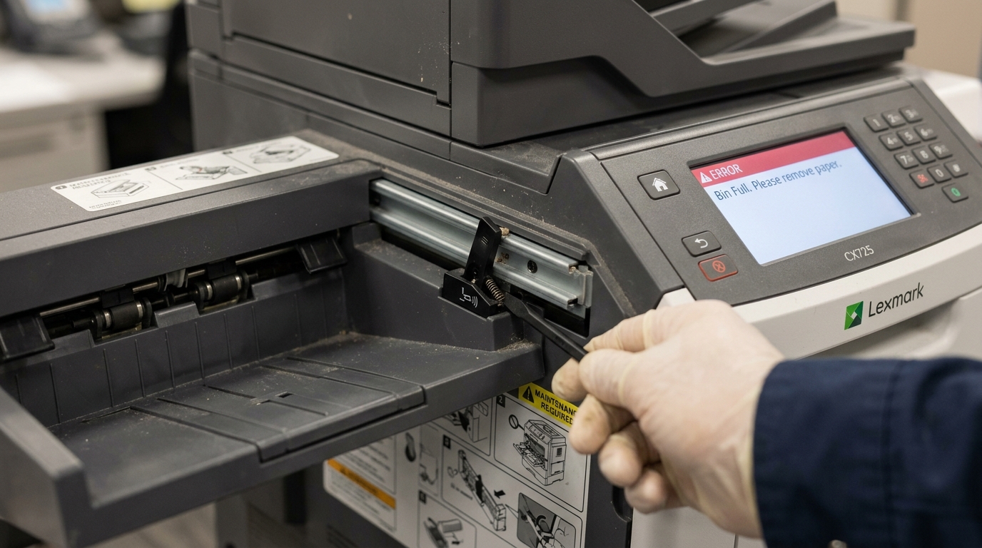
Deciphering the "Standard Bin Full" False Positive in Lexmark Printers
In the high-volume environment of enterprise document management, a Lexmark laser printer halting operations due to a "Standard Bin Full" error is a common occurrence. However, when this error message illuminates the control panel, yet the output tray (the standard bin) is completely empty, it creates a frustrating bottleneck that disrupts workflow and confounds IT support staff.
This phenomenon, known as a false positive bin full error, is rarely a complex software glitch; rather, it is almost exclusively rooted in the electromechanical mechanisms that monitor paper output. Lexmark printers employ a simple, yet critical, mechanical component known as the "exit flag" or "bin full sensor flag" to determine the capacity status of the output bin.
When this seemingly insignificant plastic component malfunctions—whether due to physical damage, dust accumulation, or simple mechanical binding—it sends continuous, erroneous signals to the printer's logic board, effectively paralyzing the device. This comprehensive guide provides a deep dive into the architecture of Lexmark's exit sensing system, offering detailed diagnostic procedures and step-by-step physical repair strategies to resolve the false "Standard Bin Full" error and restore your printer to optimal operational status.
The architecture of the bin full detection system is elegantly simple but highly susceptible to environmental interference. The system consists of two primary components: a lightweight plastic paddle (the exit flag) that rests in the path of the exiting paper, and a photo-interrupter sensor located on the logic board.
As a sheet of paper exits the fuser assembly and enters the output bin, it physically pushes the exit flag upward. When the paper clears, gravity or a delicate torsion spring returns the flag to its resting position.
The photo-interrupter consists of an infrared LED emitter and a receiver. When the exit flag is in its resting position, a plastic arm attached to the flag blocks the infrared beam.
As the bin fills with paper, the accumulating stack eventually prevents the flag from returning to its resting position. The plastic arm remains lifted, allowing the infrared beam to complete the circuit between the emitter and receiver.
The logic board registers this completed circuit as a "Bin Full" state and halts printing to prevent paper jams. A false positive occurs when the flag becomes stuck in the 'up' position, or when the photo-interrupter is compromised, continuously completing the circuit even when no paper is present.
Why This Happens: The Mechanics of Exit Flag Failure
Understanding the specific failure modes of the exit flag mechanism is crucial for effective troubleshooting. The most prevalent cause of a false "Standard Bin Full" error is mechanical binding.
The exit flag pivots on two small plastic hinges or within a specialized bracket. Over thousands of print cycles, paper dust—a highly abrasive microscopic particulate composed of cellulose fibers and filler materials—accumulates on these pivot points.
This dust mixes with ambient humidity to form a thick, frictional paste that impedes the free movement of the flag. Instead of dropping back down after a sheet passes, the flag gets stuck in the elevated position, continuously triggering the photo-interrupter.
Furthermore, aggressive attempts to clear paper jams from the rear of the printer frequently result in the exit flag being accidentally dislodged from its hinges or its delicate torsion spring being stretched or broken. If the spring is damaged, gravity alone may not be sufficient to return the flag to its resting position, especially in older machines where the plastic has warped slightly over time.
Beyond physical binding, the photo-interrupter sensor itself is a common point of failure. This sensor is highly sensitive to optical interference.
If an excessive amount of toner dust or paper debris accumulates within the U-shaped channel of the sensor, it can obscure the infrared emitter or receiver. While a blocked sensor typically causes a "Paper Jam" error (as the printer expects the beam to be broken momentarily as the paper passes), a severe accumulation of reflective dust can scatter the infrared light, causing the receiver to detect a signal even when the flag arm is blocking the direct path, leading to erratic false positive bin full states.
Additionally, environmental factors play a significant role. Printers located in areas with high humidity or significant temperature fluctuations are more prone to plastic warping.
The exit flag itself, or the chassis surrounding it, may warp slightly, causing the flag arm to drag against the housing and preventing it from fully breaking the optical beam in its resting position. Finally, while rare, a failure on the logic board itself—specifically a short circuit in the sensor input channel—can cause the printer to constantly interpret a 'high' signal from the sensor line, resulting in an unresolvable bin full error regardless of the physical state of the flag.
Step-by-Step Fix: Servicing the Exit Flag and Sensor Assembly
Resolving this issue requires a methodical approach, beginning with simple cleaning and progressing to physical realignment of the sensor mechanism. Proceed with caution, as the internal components of a laser printer are delicate.
- Power Down and Access the Output Area: Turn off the Lexmark printer and immediately disconnect the power cord from the wall outlet. Safety is paramount. Open the rear access door (often labeled the fuser access door). Locate the fuser unit (caution: it may be extremely hot if the printer was recently used). The exit flag is typically located just above or immediately after the fuser rollers, dangling down into the path leading to the top output bin.
- Locate and Inspect the Exit Flag: Identify the exit flag. It is usually a lightweight, black plastic paddle or series of prongs hanging down into the paper path. Gently push the flag upward with your finger and release it. It should move freely and instantly drop back down to its resting position under its own weight or via spring tension. If it feels sluggish, sticks, or requires force to move, mechanical binding is the culprit.
- Clean the Pivot Points and Flag: Using a can of compressed air, blow out the area surrounding the exit flag's hinges to remove loose paper dust and toner. Next, lightly dampen a long cotton swab with high-purity isopropyl alcohol (90%+). Carefully swab the pivot points where the flag connects to the printer chassis. Work the flag up and down manually to work the alcohol into the hinges, dissolving any accumulated grime. Continue until the flag swings completely freely.
- Inspect and Reseat the Torsion Spring (If Applicable): Many Lexmark models utilize a very fine, hair-like torsion spring to assist the flag's return. Inspect the area around the pivot points for this spring. If it is dislodged, use fine tweezers to carefully reseat the legs of the spring into their designated notches on the flag and the chassis. If the spring is broken or missing, the entire flag assembly or fuser unit may require replacement, as gravity alone is often insufficient for reliable operation.
- Clean the Photo-Interrupter Sensor: The most challenging step is locating and cleaning the optical sensor. The arm of the exit flag extends upward into a small, U-shaped black plastic component mounted on a circuit board. This is the photo-interrupter. Use compressed air (held completely upright to avoid spraying liquid propellant) to blow out the U-shaped channel of the sensor. If accessible, use a dry, clean swab to very gently wipe the inner faces of the sensor channel to remove any stubborn toner dust that might be scattering the infrared beam.
- Reassemble, Power Cycle, and Test: Ensure no tools or debris are left inside the printer. Close the rear access door securely. Reconnect the power cord and power on the printer. Allow it to complete its full initialization cycle. Send a multi-page test print. Observe the output bin. The error should be cleared, and the printer should successfully output the pages without halting.
Advanced Troubleshooting: Sensor Replacement and Logic Board Diagnostics
When meticulous cleaning and physical realignment fail to resolve the false positive, the troubleshooting paradigm shifts from mechanical maintenance to electronic component diagnosis. If the flag moves freely but the error persists, the photo-interrupter sensor has likely failed completely.
These sensors degrade over time; the infrared LED loses intensity, or the receiver becomes less sensitive. In many enterprise Lexmark models, the bin full sensor is integrated into a larger sensor board or even the fuser assembly itself, rather than being a standalone, easily replaceable component.
To definitively diagnose a dead sensor, a technician must access the printer's hidden diagnostic menu (the exact key combination varies by model, often involving holding specific buttons during power-on). Within the diagnostic menu, navigate to the "Sensor Tests" section.
Manually toggle the physical exit flag while observing the sensor state on the display screen. If the display does not toggle between 'Open' and 'Closed' (or '0' and '1') in corresponding rhythm with the physical movement of the flag, the sensor is electronically dead and must be replaced.
Replacing the sensor often involves significant disassembly. You must remove the outer casing, disconnect multiple ribbon cables, and extract the entire output drive assembly to access the sensor board.
This procedure should only be attempted by individuals comfortable with complex electronic repair, utilizing a grounding strap to prevent electrostatic discharge (ESD) damage to the new components. When ordering a replacement part, ensure you obtain the exact OEM part number specific to your printer's sub-model, as sensor logic voltages can vary between seemingly identical chassis designs.
In extremely rare scenarios, the failure lies not within the mechanical flag or the optical sensor, but on the primary logic controller board (engine board). If a power surge or static discharge has damaged the specific input pin on the microcontroller responsible for monitoring the bin full sensor, the board may permanently register a 'high' state, constantly triggering the error.
This can be verified if a brand new, confirmed-working sensor assembly fails to resolve the issue. Diagnosing a logic board failure is complex and typically requires a multimeter to trace the voltage from the sensor connector back to the main processor.
If a logic board failure is confirmed, the cost of the replacement board often exceeds the residual value of the printer, necessitating a complete unit replacement.
Finally, consider the operating environment. If the printer is located near a heat register, in a very damp basement, or in an industrial environment with high levels of airborne particulates (like a manufacturing floor), the exit flag mechanism will foul exponentially faster than in a clean office environment.
Implementing a rigorous preventative maintenance schedule—blowing out the output assembly with compressed air weekly—is essential in these harsh environments to prevent the recurrence of the false positive bin full error.
Frequently Asked Questions (FAQ)
I cleared a paper jam from the back of the printer, and now I have the Bin Full error. Are they connected?
Almost certainly. When aggressively pulling jammed paper out of the fuser area, it is incredibly easy to snag the delicate exit flag.
Can I just tape the exit flag down to permanently bypass the error?
No, you cannot. Taping the flag down will permanently block the optical sensor.
Is the exit flag part of the fuser assembly, or is it a separate part?
This varies significantly by Lexmark model. On many smaller desktop models, the exit flag is mounted directly to the chassis just above the fuser.
Why does the error go away when I turn the printer off and on, but returns after printing one page?
When the printer initializes during startup, it performs a basic check of all sensors. If the flag is resting slightly out of position but not fully triggering the sensor, the printer may pass the startup check.